Advanced Telescope Supplies
Australia's Premier CCD and Astro-Imaging Experts
Technical TipsBasic CCD Image Calibration Guide
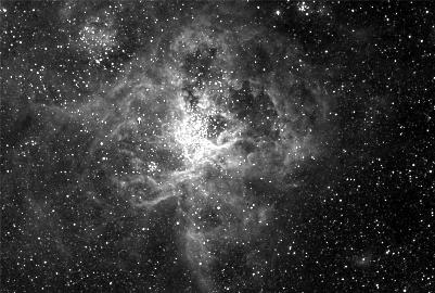
Many novice CCD users are disappointed by their initial results, as their first CCD images are often blurred, noisy and have a limited range of brightness values within the image. The image at left is a typical example of this. The image is covered with a "salt and pepper" noise pattern, and does not show much of the information which it contains.
Apart from taking an image like this object through your telescope (this is called a data or light frame), you will also need two other CCD images in order to process your "light frame".
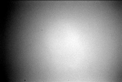
The first is called a Dark Frame (an example is pictured left), which is literally a CCD picture taken with the lens cap on (you can dispense with the lens cap if your CCD camera has a shutter)
Why would we need to do such a thing? Because the Dark frame contains a map of the thermal noise of the CCD detector. This noise will vary with the CCD temperature and exposure time, however the map will remain unchanged for any particular exposure time an temperature, hence you will be able to use it for different light frames, provided they also have the same exposure time AND were taken with the CCD camera set to the same temperature.
Many experienced CCD users build up a library of Dark Frames, so they do not have to waste precious time at the telescope taking pictures of thermal noise.
To remove the thermal noise from your "light frame", all that is required is a Dark Subtraction. This process is easily handled by most CCD camera control or Image processing software. The software subtracts the thermal noise mapped by your Dark Frame from the thermal noise and data in your light frame (thermal noise also builds up in light frames too!).
The result? We have removed the noise leaving data only!....well almost.
This leads us on to the next step....
The second type of calibration image is called a Flat Field ( an example is pictured left). Flat fields are literally pictures taken through your telescope of an illuminated, but otherwise blank screen (or field).
Again, why would we do such a thing?
The reason is, microscopic dust particles can fall on your telescope optics, CCD window or CCD itself, will cause small "dust doughnuts" on the image in combination uneven illumination from the telescope or optical system (i.e vignetting) with the centre of our image being brighter than the edges.
To remove these effects, we use the image of a blank surface to profile the dust motes and uneven illumination seen by our CCD detector.
Important note: Don't change focus, camera rotation or filter position, the Flat Field also needs to have a Dark frame subtracted from it prior to its being used for calibration.
Once we have our dark calibrated flat field, we use this image by dividing it into out light frame.
Why divide it?
Well, consider flat fielding a picture of a flat field. Each pixel value in the image, say "X" would be divided into itself, i.e X/X and produce an image full of pixels with a constant value of 1, i.e. quite featureless, which is how a blank card should look!
Again, most CCD image processing software will allow you to easily perform this operation simply by asking you to nominate an image to use as your "flat", and will use this to calibrate your light frame.
Some Further Notes: Flat fields need not be taken at the same temperature or duration of your light field. Simply adjust the exposure time so that the CCD is about 30% saturated (e.g. If the full capacity of your CCD pixels is 65,000 counts try for around 20,000). Doing so will minimise any noise introduced to your light frame by the flat field process.
Some suitable flat field targets are (in order of uniformity):
- The evening twilight sky...just make sure you don't catch any bright stars as well (very easy to do with a CCD at twilight!)
- A large, (i.e. bigger than the telescope's aperture) evenly illuminated white card or surface
- An electro-luminescent panel
- A translucent plastic "lightbox"
Once you have "calibrated" your light frame (i.e. subtracted out the thermal noise, and and compensated for uneven illumination of the CCD) you can further process the image with your image processing software.
Many programs allow you to "grey scale" or brighten the dark portions of an image, and darken the brightest parts into something which reveals much of the information contained within your original data or "light frame".
There are other techniques such as unsharp-masking, image de-convolution, digital development etc, but these all require that you first calibrate your light frame. Not doing so will exaggerate the noise and vignetting in your light frame when you apply these advanced techniques.