Advanced Telescope Supplies
Australia's Premier CCD and Astro-Imaging Experts
Telescope Optics: a technical discussion
While touched on elsewhere on this web site, the quality of telescope optics and how they are measured is often beyond the interest of first time telescope purchases. Yet for those who have owned a few telescopes over the years it can be an endless source of interest and debate amongst telescope users. Questions such as "which is better? Refractor or Reflector?" are often asked.
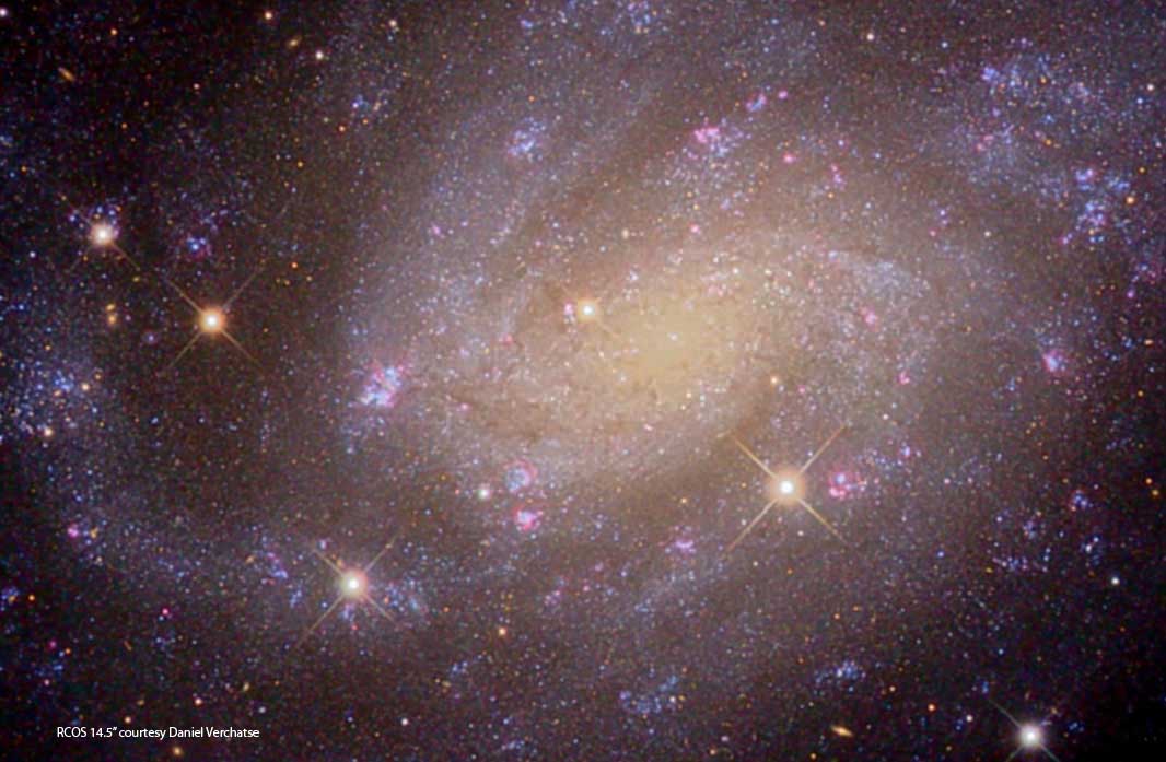
The mouse-over above is an image a galaxy known as NGC300. Even though the images were taken though equivalent aperture telescopes, they vary markedly in resolution and detail. It could be argued that the difference is due to the differing optical designs. However, this is very unlikely. Provided a telescope is well made, design differences often do not make a great deal of difference in their resulting images. Optical quality and mechanical design can make significant differences. But how to test optical quality?
Fortunately it is very easy to qualitatively test telescope optics. An excellent text on how to do this is "Star Testing Astronomical Telescopes" by Richard Suiter (Willmann Bell 1995). Much can be learned about a telescopes optics without having quantitative interferometric data.
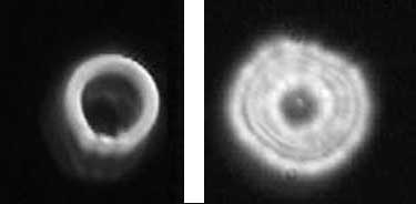
Figure 1 |
Pictured at left is are intra and extra focal images taken by the 14" Dall-Kirkham telescope used in the above mouse-over. |
|---|---|
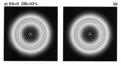
Figure 2 |
Pictured left is what a perfectly corrected telescope image should look like either side of focus (33% central obstruction, Suiter 1995) |
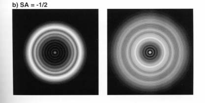
Figure 3 |
The diagram at left is also from Suiters Book, and shows what a 1/2 have spherical error intra and extra focal length images would look like. Errors of more than 1/4 wave are easily seen at focus, and would be grounds for rejecting an optical set. |
The star test will do a good job in qualitatively testing an optic, but is subject to a good deal of interpretation in quantitatively specifying any errors. Using laser light and a precision optical flat an optician can send a "reference beam" into a telescope and compare it with the beam from the telescopes optics. This creates what is known as interference fringes, which are the result of wavelengths of light constructively and destructively combining to produce reference bands, or fringes which can be accurately measured. These bands should not be confused with a much more coarse test known as a Ronchi Screen (below, left).
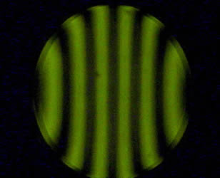 The Ronchi test is a variation on a knife edge or Foucault test, used by many amateur telescope mirror makers for over 100 years, and while it has been used to make some fine telescope mirrors, it is
again a qualitative measure of the surface accuracy of a mirror, hence the use of modern interferometric testing (image below) for very high precision optics.
The Ronchi test is a variation on a knife edge or Foucault test, used by many amateur telescope mirror makers for over 100 years, and while it has been used to make some fine telescope mirrors, it is
again a qualitative measure of the surface accuracy of a mirror, hence the use of modern interferometric testing (image below) for very high precision optics.
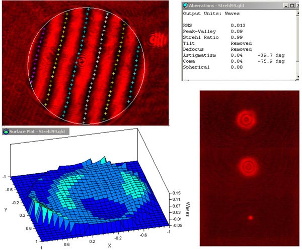
An interferometric test involves gathering several thousand data test points taken at various orientations across the entire optical surface. Computer software is then used to build up a 3D "map" of the deviations of that surface from its theoretically perfect location.
Another measure of the test data, called Strehl ratio, can be calculated from interferometric data to determine a ratio of how much light is actually being sent into focus, compared to light which is lost due to any optical imperfections. The optic below is exceedingly good, with a strehl of 0.99 or 99%. Most commercial optics are around .80 or 80%.
A value less than this generally means the optic is defective, which can also be easily picked in a star test as in figure 3 above.
 Returning then to our original question, what is better refractor or reflector? In our opinion, is does not matter! Far more important is how well made the telescope is. A poorly made telescope will have a host of problems which far outweigh any design considerations. These problems can include:
- Soft or Blurry images
- Poor image contrast
- Bloated star images or halos
- Edge distortion of star images into "comet" or "seagull" or similar shapes
- Optical alignment changes with the telescopes orientation
- Focus changes with temperature
- Poor thermal control resulting in constant tube currents that distort images.
Fortunately many telescopes do not have these problems, and manufacturers such as RCOS go to great lengths to ensure their instruments have the following properties.
- Zero Expansion Astro-Sitall Ion Milled Optics or Computer polished optics certified to at least 1/25 RMS.
- Fringe analysis and interferometric data supplied with each optical set.
- Enhanced Aluminum (SiO2/TiO2) overcoat - 96.9% reflectivity.
- Low Expansion, light weight Carbon Fiber Truss for superior performance and stability.
- Precision CNC Machined 6061 Aluminium components.
- Precision Secondary Mirror Focuser.
- 2-Stage Primary mirror baffle with internal knife-edge light stops.
- Secondary light baffle.
- Active Cooling.
- Thermally stable, "set once and forget" focus.
- Shipped fully assembled, collimated, and ready to use.
- Very low flexure rigid (rear cell) instrument adapter set
- CNC machined dust cover over primary mirror.
Ion Milling or Ion Beam Figuring (IBF) was originally developed by the Eastman Kodak Company in 1988 and became operational in 1990.
IBF is an excellent compliment to conventional figuring. The optics are first polished (ground) conventionally and then final figure is milled by the IBF.
Ion Beam Figuring works on a molecular level.
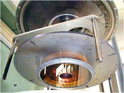
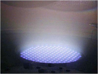
The optics are inserted into a high-vacuum chamber facing down. The IBF then directs a beam of argon ions upward to the glass, which is removed on molecular layer by layer basis.
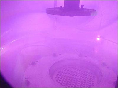
The beam itself is translated across the optical surface through a computer controlled mask, removing figuring errors and surface roughness leftover from conventional polishing.
Without question, Ion Milling is the most important breakthrough ever in optical manufacturing. Instead of conventional grinding (scratching) a mirror, Ion Milling removes glass at an atomic scale resulting in a very smooth surface. This extremely high surface smoothness reduces scatter and results in the highest contrast possible.
Ion-Milling is available for Ritchey-Chretien optics of 14.5"-32" sizes. Please call for information on larger sizes.
 |
 |
| A Ritchey-Chretien 16 inch primary mirror already figured and polished to 1/6 wave P-V is mapped by a special camera and then lowered into the chamber (with any necessary masks). | When the Ion Beam Figuring is finished, the chamber is purged and the process is complete. |
 |
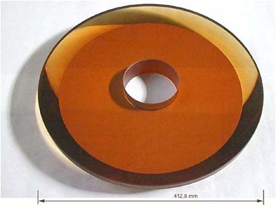 |
| A beam of argon ions is translated over the optical surface. IBF molecularly removes material from the mirror surface. | A finished 16 inch Ritchey-Chretien primary mirror. This particular mirror required only 3 iterations with the Ion-Beam. |